Section Navigation

Introduction
This module uses the foundational coding components introduced in Pathfinder 3: Programming Pathfinder in Small Basic to create basic graphics.
This module provides documented examples and source code samples that will be used to create simple graphics in Microsoft Small Basic. At the end of this module students will be able to:
- break images into small geometric shapes,
- use a grid and simple mathematics to plot image components,
- understand how to assign colour to objects,
- understand image layering, and
- use additive and subtractive methods of drawing to create more complex graphics.
Learning Goals
This module exposes students to basic computer programming concepts within a simplified and easy-to-navigate environment: Microsoft Small Basic. Students will construct programs that can display graphic objects and learn how to use additive and subtractive methods in their image construction.
Vocabulary
Guiding Questions
- Do you want to know how to draw pictures using only computer code?
Curriculum Links
This module is about learning how to draw using code, and therefore is an interesting bridge between Science and Technology, and Art. Students will expand their creativity, artistic skills, and computer knowledge and experience, and develop a greater understanding of what is possible with technology and software.
Materials
Non-Computer Activity
- Blank paper or graph paper
- Colouring utensils
- Any drawing book by Ed Emberley (or familiarity with his process)
- Example images of animals (illustrations or photographs of fish, turtle, bird, dog, etc…)
Computer Activity
- A computer with Microsoft Small Basic installed OR Internet access to the online interface
Non-Computer Activity
Drawing Simple Animals with Geometric Shapes
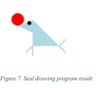
Using Ed Emberley’s drawing method, provide several examples in his style. For example, Figure 1 is a seal created using this method.
By drawing on graph paper students can make use of the grid as reference points to re-build their drawing with code..
GraphicsWindow.Width = 300
GraphicsWindow.Height = 300
GraphicsWindow.BrushColor = "Red"
GraphicsWindow.FillEllipse(10,10,140,140)
GraphicsWindow.FillEllipse(150,10,140,140)
GraphicsWindow.FillTriangle(10,80,150,290,290,80)
Computer Activity
Programming in Small Basic – Introduction to Drawing Pictures
This module explains how to draw pictures in Microsoft Small Basic, and assumes students are familiar with the Small Basic programming environment and have tried a few of the tutorials from the Introduction to Small Basic module.
In this module students will draw pictures using basic shapes, explore options for line and fill colour, learn to layer shapes, and use a grid for laying out pictures. Drawing through computer programming is a fast and fun way to learn programming, because you can test frequently and see your results after each line of code. Once you learn how to use the drawing tools in Small Basic you can create your graphics for your own game.
Graphics and Drawing
The GraphicsWindow drawing actions are easy to use and very versatile for creating graphic images. This section introduces how to draw basic shapes, and combine them to create complex shapes for game graphics. Examples in this module use a standard window that is 300px by 300px square, but feel free to experiment with different sizes.
Let’s start! Open Small Basic. By default, Small Basic always opens with a new untitled document. To set the window size to 300px X 300px, enter:
GraphicsWindow.Width = 300
GraphicsWindow.Height = 300
Now let’s try some shapes!
A Rectangle
The DrawRectangle method allows us to draw a rectangle on our screen. Four parameters are required: the positional coordinates of the shape from the left and top of the window (x and y respectively), and the rectangle’s width and height:
GraphicsWindow.DrawRectangle(x, y, width, height)
To tell our program to draw a rectangle 30 pixels wide by 40 pixels high, and placed 10 pixels from the left and 20 pixels from the top of the window frame, enter the following line of code:
GraphicsWindow.DrawRectangle(10,20,30,40)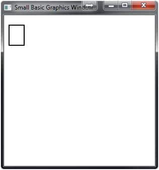
Hit Run(F5), and the result should look similar to Figure 1.
This is a great start. To change the colour of the frame use the PenColor command. Add the following line of code immediately before your DrawRectangle:
GraphicsWindow.PenColor = “IndianRed”
GraphicsWindow.DrawRectangle(10,20,30,40)
Run this code and now the border is a dark red. Let’s try this example; change “IndianRed” to “#FF69B4”:
GraphicsWindow.PenColor = “#FF69B4”
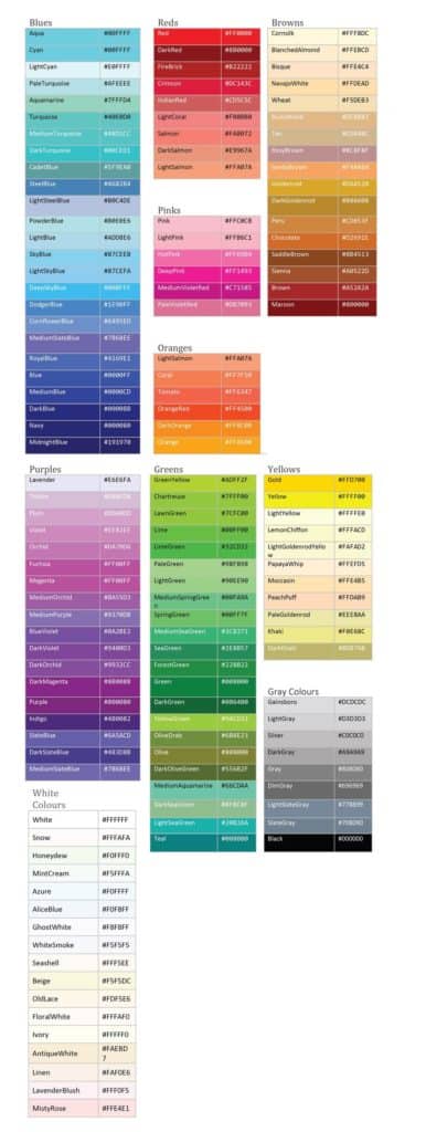
GraphicsWindow.DrawRectangle(10,20,30,40)Run this code and now your rectangle is hot pink! Those letters and numbers represent a hexadecimal value that specifies the amount of red, green, and blue that are combined to create a specific colour. Small Basic accepts both hexadecimal values and colours by name. Refer to the colour charts at the end of this module to see a list of hex values and their associated colour.
For a complete list of the 142 named colors and their hexadecimal codes see the appendix at the end of this module.
A primitive refers to the simplest geometric shape and in Small Basic includes the shapes: ellipse, rectangle, and triangle.
Now that we can draw a rectangle and change the frame colour, how do we fill it? In Small Basic, each of the primitives (ellipse, rectangle, and triangle) has two commands: one that draws a frame of the shape, and one that draws a filled version of the shape. For filled shapes, the the “pen” needs to be changed to a “brush”. Change DrawRectangle to FillRectangle, and PenColor to BrushColor:
GraphicsWindow.BrushColor = “#FF69B4”
GraphicsWindow.FillRectangle(10,20,30,40)
This program yields a filled, hot pink rectangle. But how can we change the border of our filled rectangle? We need to combine both of these commands.
Remember:
- Use PenColor with Draw[Shape]
- Use BrushColor with Fill[Shape]
DrawRectangle only draws the “border” of a rectangle or, more precisely, a border with a transparent filling. Whereas, FillRectangle only draws the fill of the shape with a transparent border. So to create a rectangle with a border we need to write both. Try the following example:
GraphicsWindow.PenColor = "Black"
GraphicsWindow.DrawRectangle(10,20,30,40)
GraphicsWindow.BrushColor = "HotPink"
GraphicsWindow.FillRectangle(10,20,30,40)
Run this code and the result is a hot pink rectangle with a black border. Now let’s try adding some more shapes, like an ellipse or circle.
An Ellipse
Using the same process as for the rectangle, let’s add an ellipse that is also 30 by 40 pixels. We will place this shape 50 pixels from the left and 50 pixels from the top. Enter the following and you should get what you see in Figure 2.
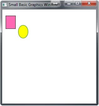
GraphicsWindow.PenColor = "Green"
GraphicsWindow.DrawEllipse(50,50,30,40)
GraphicsWindow.BrushColor = "Yellow"
GraphicsWindow.FillEllipse(50,50,30,40)
This method of creating shapes fairly straightforward, and once you get the hang of it, it is easy to draw simple pictures. The triangle is trickier, so let’s look at that next.
The Triangle
The triangle primitive is tricky because we have to know where each corners will be placed. The DrawTriangle method follows this pattern:
GraphicsWindow.DrawTriangle(x1, y1, x2, y2, x3, y3)X1 and Y1 are the X and Y coordinates of the first point of the triangle, X2 and Y2 the second, and X3 and Y3 the third. Add this to your program:
GraphicsWindow.PenColor = "Blue"
GraphicsWindow.DrawTriangle(30,30,80,80, 50, 100)
GraphicsWindow.BrushColor = "LightSkyBlue"
GraphicsWindow.FillTriangle(30,30,80,80, 50, 100)
There are three primitives now, but our triangle is partially overlapping the ellipse and rectangle. This is an example of layering.
Layering
Small Basic processes each line of code in sequence, so if you draw a blue square followed by a yellow square with the same shape and position, you will only see the yellow square. This is because the instructions for the yellow square occur after those for blue square. For example, copy and run the following code:
GraphicsWindow.BrushColor = "Blue"
GraphicsWindow.FillRectangle(10,20,30,40)
GraphicsWindow.BrushColor = "Yellow"
GraphicsWindow.FillRectangle(10,20,30,40)
The visible result is a single yellow rectangle. The other rectangle is there, but we can’t see it. It does not matter what colour we programmed in the first line, because the second FillRectangle is the exact same shape and position, and covers the shape placed under it.
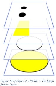
Let’s use this idea of layering to draw a simple happy face. We will draw a big yellow circle for the face, two smaller black circles for eyes, and a half moon shape for the mouth. Although the mouth could be drawn a number of different ways, we will use a rectangle layered over an ellipse to achieve the effect we want (see Figure 3). Close the current code window, create a new blank window, and add the following:
GraphicsWindow.Width = 300
GraphicsWindow.Height = 300

'Draw a big yellow circle with a black border
GraphicsWindow.PenColor = "Black"
GraphicsWindow.DrawEllipse(10,10,280,280)
GraphicsWindow.BrushColor = "Yellow"
GraphicsWindow.FillEllipse(10,10,280,280)

'Draw a smile
GraphicsWindow.DrawEllipse(50,50,200,200)
GraphicsWindow.BrushColor = "Yellow"
GraphicsWindow.FillRectangle(48,48,210,110)

'Draw the eyes
GraphicsWindow.BrushColor = "Black"
GraphicsWindow.FillEllipse(75,75,50,50)
GraphicsWindow.FillEllipse(175,75,50,50)
Let’s examine how each line of code works.
The Head
First we set the width and height of our window. Then we drew the head by setting the PenColor to Black and drawing an ellipse 280px wide and 280px high. By making the head ellipse smaller than the window, it allows for a margin of space around it. Playing with graphics mathematics is explained in greater detail later in the document. For now, just enter the provided code.
The Smile
Next we set the BrushColor to Yellow and drew another black ellipse. But this ellipse is only 200px wide and high, and placed at position 50, 50. Running the program at this stage yields a big yellow circle with a smaller black ring inside it. To make this black ring into a smile, we drew a yellow rectangle to cover the top half of it (GraphicsWindow.FillRectangle(48,48,204,104)).
We positioned this yellow rectangle at (48, 48)—not (50, 50)—and sized it to 204px by 104px. If we had made the rectangle exactly half the height of the inner circle (100px), and the full width (200px), we still might see some a bit of the circle underneath, so to cover the top half completely, we made our rectangle slightly larger, and positioned it a couple pixels closer to the top and left of the window. Run your code at this point and you see a Yellow head with a smile – all we need now are the eyes. Figure 3 illustrates how each line of code is applied in a sequence of layers.
The Eyes
To position the eyes evenly on the head, you can use a pen and paper and calculate the coordinates, or you could simply place the eyes, run the code, and adjust the X and Y position values until you find a good placement.
Keep in mind that in Small Basic, the coordinates are always referenced from the top left corner of the object—not the center—which means you need to know the width and height of your objects and factor that into your calculations.
Now that the face is complete, you can understand how layering is used to create a picture. We used this to “color over” a part of the drawing to get the effect we wanted. Let’s try another example, this one is a bit easier: a heart.
A Heart
Looking at a heart shape, you can see how we might be able to break it down into simpler shapes: it looks like two half circles side by side and an upside-down triangle. So, let’s do exactly that. Start a new code window and type the following:
Run this code and the result is a heart-like shape (Figure 3), but the circles make “humps” at the sides of our heart.
To remove those, we will draw a white rectangle over the bottom half of the circles, before drawing the triangle. Insert the following code after the commands for the two circles:
GraphicsWindow.BrushColor = "White"
GraphicsWindow.FillRectangle(0,80,300,220)
Note, that every time you want to change your colour you have to set the BrushColor to the colour you want to use. In this case, we want to draw two red circles followed by a white rectangle, and then a red triangle. Our final code looks like this:
GraphicsWindow.Width = 300
GraphicsWindow.Height = 300
GraphicsWindow.BrushColor = "Red"
GraphicsWindow.FillEllipse(10,10,140,140)
GraphicsWindow.FillEllipse(150,10,140,140)
GraphicsWindow.BrushColor = "White"
GraphicsWindow.FillRectangle(0,80,300,220)
GraphicsWindow.BrushColor = "Red"
GraphicsWindow.FillTriangle(10,80,150,290,290,80)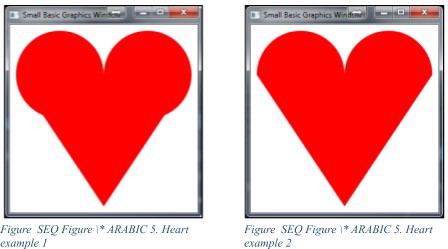
Though this heart has two sharp corners where the triangle meets the half circles (see Figure 4), it shows how easy it is to combine shapes to make interesting and more complex images.
Working with layers is an essential skill to master, because as shapes are added, it becomes more difficult to “block” other shapes. By building images from simple shapes, you will also improve your math skills, as placing shapes often requires simple addition and subtraction.
At this point, by using primitives and layers, you have enough information to design your own pictures. Another tool that can help with creating graphics is the line command.
The Line
Much like the DrawTriangle command, DrawLine uses the coordinates of the GraphicsWindow, using the structure:
GraphicsWindow.DrawLine(x1, y1, x2, y2)Where X1 and Y1 are the X and Y coordinates of the start of the line, and X2 and Y2 the end point.
Note that line colour is set by the PenColor command.
Let’s try drawing some lines in another example.
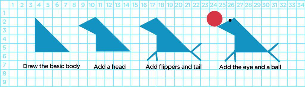
Another Example – The Seal
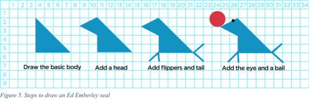
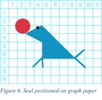
Let’s create a seal using Ed Emberley’s drawing method. Figure 5 shows how the seal is constructed from simple geometric shapes. Repositioning the final image into an area where we can reference the row and column numbers of the graph paper, we should be able to create this seal with relative ease. Each square in this grid (Figure 6) represents 10 pixels, so the square at the intersection of 1 X and 1 Y on the grid translates to 10 X and 10 Y in our window. As you practice transferring images drawn on graph paper into Small Basic, the process of measuring and placing your shapes will become easier and more intuitive.
Let’s being by setting our image size:
GraphicsWindow.Width = 120
GraphicsWindow.Height = 120
As the seal is primarily LightBlue, and we will be using both lines (DrawLine) and shapes (FillTriangle) for our seal, we need to set PenColor and FillColor to LightBlue.
GraphicsWindow.PenColor = "LightBlue"
GraphicsWindow.BrushColor = "LightBlue"
Now that we’ve established that, we can begin to draw the body. The coordinates for the first triangle go from the corner of 5,3 to 5,7 and then 9,7; we simply need to add a zero to the end of each coordinate to make the image large enough to see when we run it:
GraphicsWindow.FillTriangle(50,30,50,70,90,70)Then add the head:
GraphicsWindow.FillTriangle(50,30,30,40,50,50)The front flippers:
GraphicsWindow.DrawLine(50, 70, 40, 80)
GraphicsWindow.DrawLine(50, 70, 50, 85)
The tail:
GraphicsWindow.DrawLine(90, 70, 100, 60)
GraphicsWindow.DrawLine(90, 70, 100, 80)
The eye (switching the fill colour first):
GraphicsWindow.BrushColor = "Black"
GraphicsWindow.FillEllipse(42,32,6,6)
The ball:
GraphicsWindow.BrushColor = "Red"
GraphicsWindow.FillEllipse(18,20,19,19)
The position of the eye and ball can be difficult to gauge from the reference drawing, so adjust the x and y coordinates until they are positioned properly. Figure 7 shows what the seal looks like when we run this code.
Mathematics, Grids, and Coordinates
Mathematics
Building pictures in this way can be very rewarding as it develops your programming skills quickly, and gives you the tools to create some really great pictures. To become truly adept at picture construction, it is important to take the time to determine where your shapes will be placed. Drawing out your designs, and using a ruler to work out some of the essential measurements first, will be very helpful when coding your image.
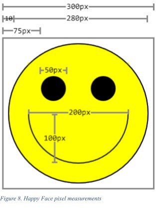
Let’s examine the Happy Face example. The head circle was 280 pixels. To get 280, we took the total width and height of the window (300px x 300px), and created a 10 pixel margin of space around the head. So, the width (300) less 10px on the right and left (20) leaves us with 280 pixels remaining. Since we were dealing with perfectly round circles, the same was applied to the height measurement. And, because we wanted it centered, we placed it at the position of 10, 10. This is fairly straightforward, but what happens when we need to place objects in relation to other shapes, and not in relation to the top left corner?
The eyes of our Happy Face, for example, take a bit more thought. Drawing this out on paper first, as in Figure 8, illustrates where the various shapes are in relation to the edges and center. Doing this pre-planning and noting key locations saves lots of time when you program it.
Grid
All of the coordinates and shapes exist within an invisible grid of pixels, the size of which is established when you set your GraphicsWindow. So, planning your picture with graph paper is a very useful exercise. When deciding on a picture size, it works best if everything fits into a grid that is divisible by 5 or 10. For example, we are working with a window that is 300 pixels square, or 300 pixels wide and 300 pixels high – so we could plan our drawings on graph paper using 30 x 30 grid, where each cell represents 10 pixels.
Coordinates
As mentioned previously, in Small Basic, ellipses and rectangles are placed in the GraphicsWindow using the top left corner as the origin point. This means if you want a shape to be centered on the screen you need to determine how much to offset the shape so that the center of the shape ends up in the center of the window. Let’s look at the inner circle from our happy face. It was a 200px circle drawn into a 300px window. As we move our X (horizontal pixel) and our Y (vertical pixel) coordinates away from the top left, they increase in value, up to 300. This means that 0,0 is the top left (the origin) and 300, 300 is the bottom right; therefore the center is 150, 150. So let’s use this information and figure out what the centre-point is for our 200 px circle.
The easiest way to determine where to place the circle is to figure out how much “empty” space is left if we placed the circle in the top left corner, and then move the shape half of that distance in both directions. In our example (see Figure 8), if we placed our circle at 0,0 we will have 100 px of empty space on the right and bottom sides.
If we then move our circle half of this distance (50 px) to the right and bottom, to the coordinates 50,50, it will be perfectly centered. This may seem convoluted, but if you use graph paper to plot it out it will be easier to visualize.
Efficiency
Programming efficiency means using as few lines of code as possible to achieve your objective. Sometimes you will need many lines of code, for instance when you have many colours. In Small Basic, every change in colour needs to be specified, which adds extra lines of code. If it’s possible to do so, arrange your drawing instructions so that you draw all the objects with one colour first, then move on to the next colour. For an example of this, see the following module on Pixel Art.
Conclusion
Drawing your own pictures allows you to customize your games to make them even more engaging. Instead of using pictures from others – be an artist and make your own. You can make them as detailed, realistic, and colourful as you want. When you look at digital pictures and graphics, you see that they are made up individual pixels of colour. You can program your graphics to look exactly like these kinds of pictures. Experiment and have fun! If you enjoyed this module, or like drawing graphics using blocks, then you will love the Small Basic – Pixel Art module. Give it a try!
Resources
Additional Resources
- Small Basic Getting Started Guide
- Introducing Small Basic Full Guide (PDF)
- Online Tutorials
- Program Gallery – includes Small Basic examples for things specific to games, math and science applications, and graphics
Social Media Resources
As students advance, they can look for examples from professional pixel artists, such as:
- Chris Thompson at Lumiko in Australia
- Ariel Wollek from Israel
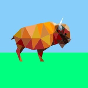
Low-poly art is interesting as images are constructed using only triangles or angular geometric shapes.