Section Navigation

Introduction
Students will be introduced to a technique for 3D modeling using Blender. Students will be encouraged to take these skills and model their own ideas. At the end of the module students should be able to create something symmetrical in 3D.
Learning Goals
With this course we will learn how to:
- Navigate in 3D space
- Create and model a mesh
- Use modifiers to optimize time
Vocabulary
ViewPort - This is where we see all of the objects of our scene.
Axis - Axis’ are imaginary lines that help us and the computer navigate 3D space.
Orbiting - Rotating our view around a fixed point or object.
Panning - Sliding the view up down left and right.
Pivot Point - The red blue and green arrows that appear on an object when it is selected. Usually the center of an object and is where the object is moved, rotated or scaled from.
Translate - Sliding an object in 3D space.
Mesh - A mesh is a collection of vertices, edges, and faces that describe the shape of a 3D object.
Vertex - A vertex is a single point (the plural of vertex is “vertices”).
Edge - An edge is a straight line segment connecting two vertices.
Face - A face is a flat surface enclosed by edges (some other applications call these “polygons”).
Polygon - A shape consisting of 4 or more sides.
Increment - Snap to grid points.
Guiding Questions
- Can anyone give an example of when they’ve seen a 3D character in a film, television show or video game?
- How did you know it was in 3D?
Curriculum Links
This module provides an opportunity to address curriculum expectations in the Science, Computer Studies and Math Grade 9 to 12 expectations. In particular, students will have an opportunity to develop spatial thinking skills, investigate geometric relationships and use a new software program (Blender). This assignment will also demonstrate how art and engineering come together to create 3D characters and objects when telling a story.
Materials
- Blender – Download Blender
- Paper
- Mirror
Non-Computer Activity
Complete The Drawing
With a piece of paper have the students draw a line down the center of it. Then have students draw only half of an object. I can be any object or a geometric pattern. Then place the mirror along the line. This object will be what students will create in Blender.
Computer Activity
The following is a list of short-cuts or ‘hotkeys’ for the keyboard when using Blender for this lesson.
- Select Objects: RMB (right mouse button)
- Orbiting: MMB (middle mouse button (the scroll wheel clicked)) and drag
- Panning: shift + MMB
- Zooming: middle scroll wheel (or CTRL + MMB + drag)
- Select All: A
- Remove Objects: X
- Toolbar: T
- Translate: G
- Undo: CTRL + Z
- Redo: shift + CTRL + Z
- Add Objects: shift + A
- Edit Mode: tab
- Switch Between Vert/Edge/Face: CTRL + tab
- Knife Tool: K
- Extrude: alt + E
- Toggle Snaps: shift + tab
- Snap Element: shift + CTRL + tab
A Quick Primer
Before we move forward the first tip I can give is that Ctrl+Z And Ctrl+S are your best friends.
Ctrl+Z is undo, it can take us back many steps if we happen to make a mistake. It however has some limits. The number of undos is set by the preferences (Ctrl+Alt+U) under the Editing Tab. By default the Undo steps are set to 32. I like to run it at 200, but this will depend on the machine and our confidence.
Side note, if you make a mistake, and have undone too far we can step forward, so long as you have not made any changes since pressing Ctrl+Z. Just Press Shift+Ctrl+Z to redo that edit.
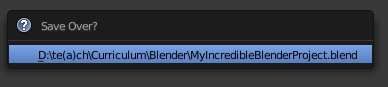
Ctrl+S the command to save quickly. Saving often is a great idea, 3D modeling programs have a reputation to suddenly shutdown and users can lose any progress made. If you want to experiment or try something new, it is best to save before you do. Let’s save our file now and give it a name.
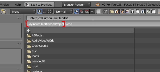
Now when you press Ctrl+S a prompt will come up to make sure you want to save over our last save. We can either click the blue section, which will have we save over the old file or we can press Shift+Ctrl+S and save a new file by renaming it to something else.
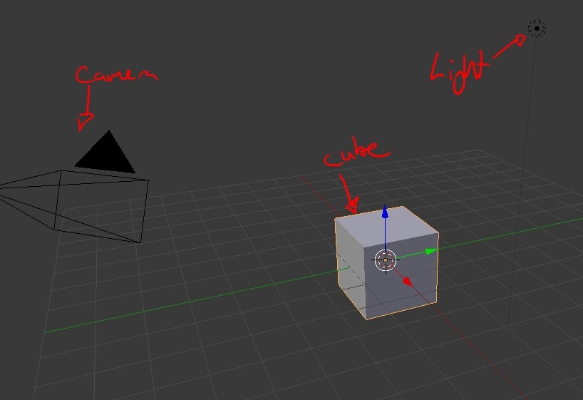
To begin set Blender to Factory Settings. Under File (top left of our screen) select Load Factory Settings. This should display a camera, light, cube, and a grid.
The Viewport
This is our largest window and is where most of the action will happen. Our intuition may have us use the LEFT mouse button (LMB) on these objects to select them. That actually has placers the 3D cursor, which is a powerful tool.
The 3D Cursor
The 3D cursor is very helpful tool. One of its functions is to be the spawn point for objects that are added to the scene. It can also act as a pivot point for the objects.
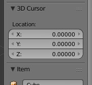
To put the 3D cursor back we’re going to have to open the Viewport Properties menu. Press N for the tab to appear. This window has some great functionality. Let’s scroll down a bit and find the 3D Cursor options. Under Location set the X, Y and Z to 0.
Scene Navigation
These 3 options will help with navigating through the scene and with viewing the model from any angle:
- Orbiting – MMB and drag (or Alt + LMB)
- Panning – Shift+MMB (or Alt + LMB)
- Zooming – middle scroll wheel (or Ctrl + MMB + drag)
Let’s Make An Object
Most objects are symmetrical on one axis or another. With Blender to save time and the program can do some of the heavy lifting.
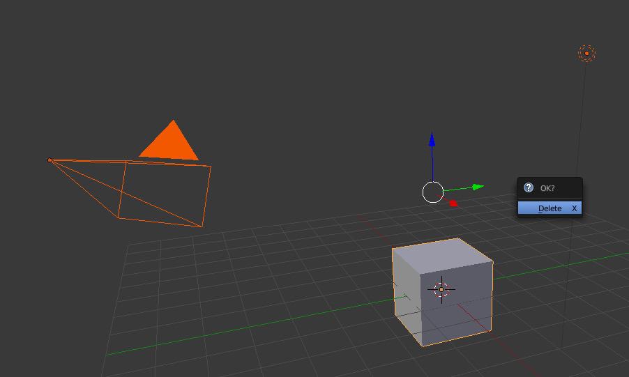
To start let’s press the A key to select everything in the scene and press X and click Delete to clear the scene.
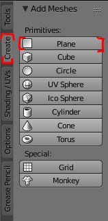
We’ll need a plane to start. Go to the Create tab on the left and press Plane.
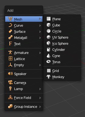
OR Press Shift+A and select Plane from the menu that pops up.
With the plane object selected (it should be highlighted with orange and have the 3 arrows on it) let’s look at the Properties window.
and switch to the Modifier tab.
Once there left click on the drop down Add Modifier and add a modifier called Mirror.
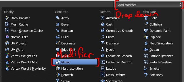
A modifier will now be added to the modifier stack, here we can decide:
- Which axis to mirror on.
- Whether or not the two halves are to be directly connected.
- How close vertices need to be before they merge into one.
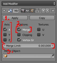
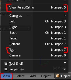
Just leave the default settings for this project. Set up the Viewport to look straight down on the plane. This helps with translating vertices. To adjust the Viewport to a top down view and into orthographic (straight on view without any perspective) open the view menu.
Now if we press G to translate we don’t have to worry about that pesky 3rd dimension.
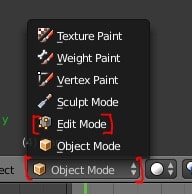
To start manipulating elements of the plane get into Edit Mode. Change this by clicking the drop down menu that says Object Mode and selecting Edit Mode from the options that appear or press tab and hop right into Edit Mode.
Snap tools make aligning things much quicker. The snap tool looks like a magnet on the Toolbar of the 3d view. Either click the magnet or press Shift+Tab to activate it.
It has several settings in the drop down that elements can snap to. Stick with Increment (which is the grid spacing size) for now.
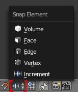
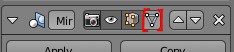
Also, turn on Snap to absolute grid alignment by clicking here:

Use the Knife tool from the Toolbar on the left or press K to have it activate.
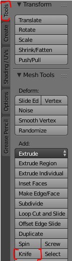
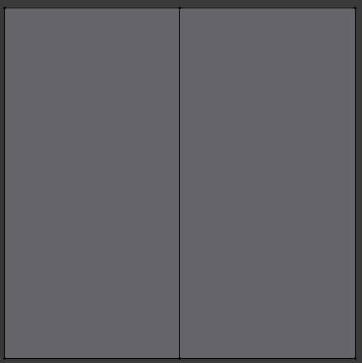
Now cut a line straight down the middle, just Left Click once at the top near the middle of the plane and once at the bottom. Vertices are created wherever clicked and an edge is created between 2 vertices. Once the plane is sliced press the Spacebar or Enter to confirm that the line created is what we want. To cancel just Right Click and try again.
Now turn off the snaps by clicking the magnet or by pressing Shift+Tab. With the Knife tool draw an image on the plane. After a few cuts notice that nothing has been mirrored.
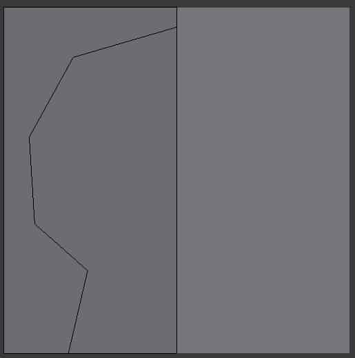
In the Mirror module click the Adjust edit cage to modifier result button.
Now it will look like this.
Make a few more cuts to give the image some teeth.
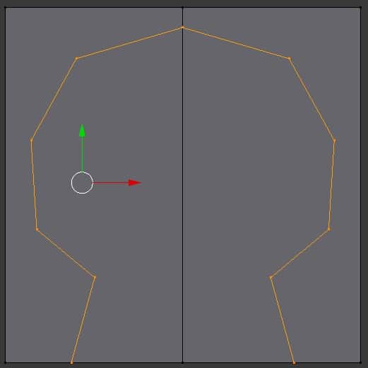
To get the teeth just right use the translation tool by Right Clicking a vertex, pressing G (or go to Translate in the toolbar on the left) and moving the mouse around to place it in a new spot.
To cut in the eyes make a line that builds off of the skull. When finished the program might add a line that was not intended. Correct it later if need be.
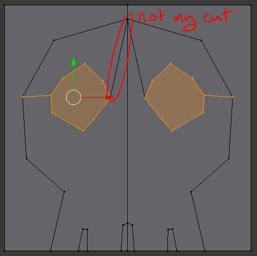
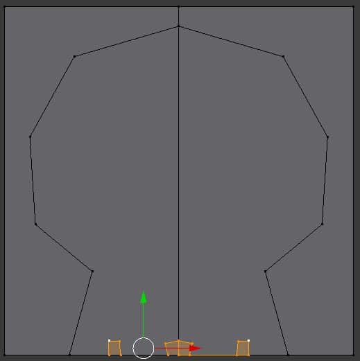
Now do the same for the nose.
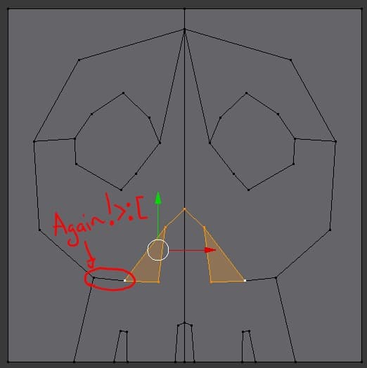
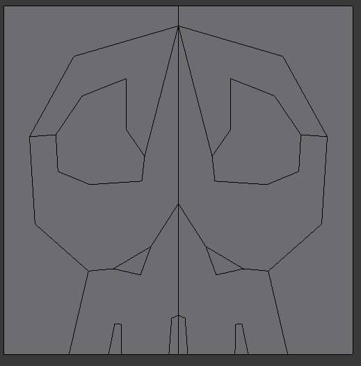
Now for some prettification with the translation tool.
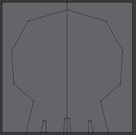
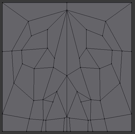
Turning every shape into either a four sided polygon or at minimum a triangle. This will make Blender and our collective parents/guardians proud. Blender works best with quads (four sided shapes) or triangles.
image
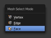
Now switch to Face selection mode either by using the element selection bar.

or by pressing ctrl+Tab
Now select the skull by holding Shift and Right Clicking all of the faces that made it up.
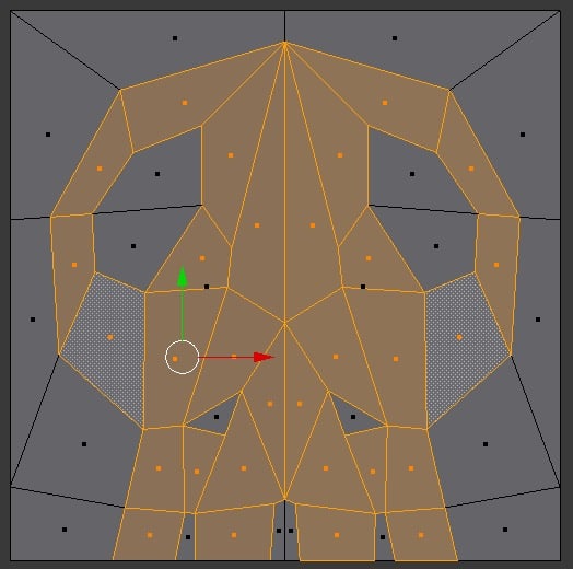
And use the Extrude Region tool in the Toolbar on the left.
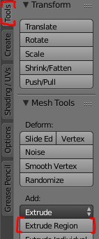
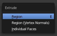
or press Alt+E and click Region
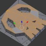
And watch as we move our mouse and make our creation rise, Rise, RISE!
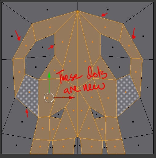
Oh wait, no it didn’t rise because we need to move our view a little. These little half dots that appeared do indicate that some form of element has been created (a couple of faces in this case). Right Click to cancel any movement we may have made and then pan the viewport with middle mouse click. Then we can either Left Click the blue arrow of the Pivot Point for translation or press G and then Z to constrain translation to the z axis.
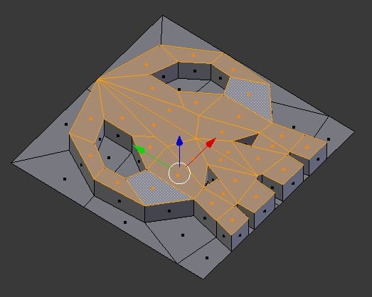
Woohoo! We did it! Now save this puppy and reflect on all that we have done today. Were going to use this model to build into another lesson.
Conclusion
Learning Blender takes time to explore and practice. Take a moment and check out some examples of artist work in the feature reel on the Blender website.
Resources
Additional Resources
- ArtStation is great to see work from some top 3D/2D professionals (don’t be discouraged, these professionals have been practicing for years to get this good).
- Blender Tutorials are great for beginners.
Social Media Resources
- Blender on Twitter – @blender_org
- BlenderDeveloper on Twitter – @blender_dev
- Blender News on Twitter – @BlenderToday
You might also like

Building A House In Unreal 4 Series
In this lesson plan series, author Leah Jackett takes students and teachers through a introduction to Unreal 4, how to plan and build a house in Unreal, and add assets into your created scene.

Introduction To Blender: Part 2
 Grade 9 – Grade 12
This lesson introduces new tools in Blender. Students will create a final project in Blender.
Introduction To Blender: Part 1
Grade 9 – Grade 12
Blender is a 3D modelling program and can be very complex if you don’t know what menus to use. Learn how to navigate Blender and create 3D models.
